
Who Should Read What? (Quick Persona Guide)
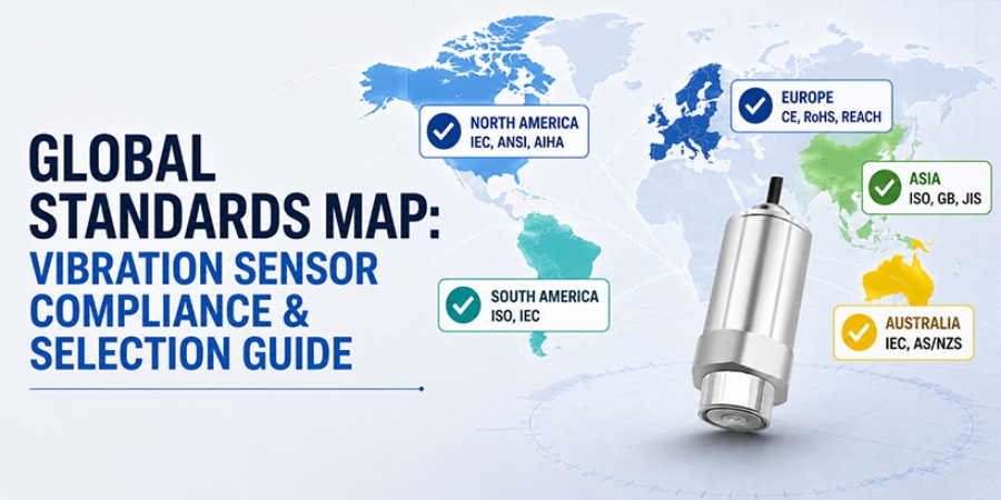
- End-Users & EPC Contractors: Focus on Standards Map to confirm your project's compliance basis.
- Equipment OEMs & System Integrators: Jump to Quick-Table & OEM Protocol & Sampling Support.
- EHS & Safety Officers (Hazardous Areas): Review the Ex d Installation Warning & ATEX specs in Section 2.
- Procurement Managers: Go straight to FAQs for Lead Time, SASO/EAC, and DDP shipping details, then submit your request in Section 5.
Table of Contents
- Global Standards "Map" for Vibration Sensor Selection
- "Four-in-One" Compliance Quick-Table for Vibration Transmitters
- Vibration Sensor Installation Support for Two Customer Types
- Vibration Transmitter Selection FAQ
- Action Entry
Global Standards "Map" for Vibration Sensor Selection
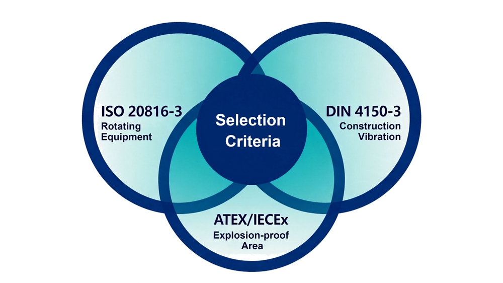
Most industrial vibration monitoring projects around the world follow just three standards. These three cover more than 95% of real‑world applications. Find your project requirements below and go straight to your standard.
| Attribute | ISO 20816‑3 (formerly ISO 10816) |
DIN 4150‑3 | ATEX / IECEx |
| Focus | Health monitoring for rotating equipment | Evaluating construction vibration effects on buildings | Fixed vibration monitoring in explosive atmospheres |
| Scope | Vibration severity for motors, fans, pumps, compressors, and other rotating machines | Damage risk to nearby buildings from pile driving, blasting, and tunneling | Online monitoring in petrochemical refineries, underground coal mines, paint shops, and grain dust areas |
| Key Metrics | Velocity RMS (mm/s). Four‑zone evaluation: A / B / C / D | Peak particle velocity (PPV) in mm/s. Limits depend on building type and frequency band. | Ex d IIC T6 flameproof certification. T6 rating means maximum surface temperature ≤ 85 °C, the highest safety level. |
| Hardware Requirements | Frequency response 10 Hz – 1 kHz; built‑in high‑pass filter; full‑band error ≤ ±5% | Frequency response 1 Hz – 80 Hz; sensitivity ≥ 1000 mV/g; resolution ≤ 0.001 mm/s | Flameproof enclosure (Ex d IIC T6); no barrier needed. Threaded mounting is mandatory – magnetic or adhesive bases are not permitted in hazardous areas. |
| Who Uses It | Maintenance teams, OEM factory testing | Civil monitoring, third‑party inspection teams | EHS teams in petrochemicals, explosion‑proof retrofitters, oilfield service providers |
| Common Mistake | Using a broadband accelerometer that starts at 0.5 Hz. Ground vibration and airflow noise get mixed in, and false alarms skyrocket. | Using a general‑purpose sensor that starts at 10 Hz to measure 1–5 Hz signals. The amplitude drops 60–70%, and the data has no legal weight. | Using an ATEX certificate directly for an IECEx project. Most owners and consultants will not accept it. |
Looking for a complete product overview? Browse our full Industrial Vibration Sensors Catalog to compare all ISO, DIN, and Ex-certified models side by side.
Vibration Sensor Frequency Response: The First Red Line
A vibration sensor is basically a spring‑mass system. ISO 20816 requires 10 Hz – 1 kHz because rotating equipment fault frequencies (unbalance, misalignment, bearing faults) all fall in this range. Signals below 10 Hz almost always come from external structure vibration or airflow. If those get in, false alarms jump.
Similarly, construction blasting energy is concentrated at 2 Hz – 20 Hz. If you use a sensor that starts at 10 Hz, it is not a matter of accuracy — it simply cannot physically measure those low frequencies.
Ex d Flameproof Vibration Sensor Installation Warning
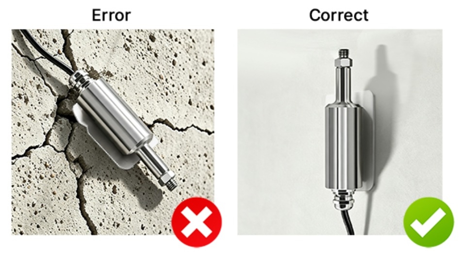
For Ex d flameproof installations, the sensor housing must remain intact, and the threaded connection must be properly sealed. Magnetic or adhesive mounting is strictly prohibited in hazardous areas. We provide detailed installation guidelines to ensure full compliance.
"Four-in-One" Compliance Quick-Table for Vibration Transmitters
Selecting the right vibration sensor starts with matching your application to the correct standard. The table below summarizes the three most frequently used standards — ISO 20816‑3, DIN 4150‑3, and ATEX Zone 1 — along with their critical technical requirements, available stock models, included documentation, and essential installation tips. Review the rows carefully to avoid common pitfalls.
| Standard | Key Technical Requirements | In‑Stock Model / Availability | Documents Included | Installation Tips |
| ISO 20816‑3 | 10 Hz – 1 kHz; range 0–50 mm/s; output 4–20 mA or RS485 | 4-20mA Vibration Transmitter | Point‑by‑point calibration curve; CE report | Mounting surface roughness ≤ Ra 3.2; apply thin silicone grease; thread M10 × 1.5; shield grounded at control cabinet end |
| DIN 4150‑3 | 1 Hz – 80 Hz; sensitivity ≥ 1000 mV/g; resolution ≤ 0.001 mm/s | Available via Inquiry only (custom low‑frequency kits) | Low‑frequency calibration data (1/5/10 Hz deviation); CE & IP68 reports | Magnetic base holding force ≥ 120 N; use adhesive base on rough concrete; cable exits downward to prevent water ingress |
| ATEX Zone 1 | Ex d IIC T6 flameproof; no barrier needed | Explosion Proof Vibration Transmitter | Original Ex d certificate; IP67 report; installation guideline | Must use threaded mounting in hazardous areas; magnetic base is prohibited; cable gland must be Ex‑certified |
Vibration Sensor Calibration: Single-Point Certificate Is Not Enough
Many suppliers only give a single‑point calibration at 50 Hz. But rotating equipment faults often show up at 800 Hz (early bearing spalling). Every sensor we supply ships with a 10 Hz – 1 kHz point‑by‑point frequency response curve. This ensures no sensitivity drop at high frequencies, so you do not miss high‑frequency faults.
Vibration Monitoring Additional Notes
- Frequency response mismatch is the most common selection error.
- If the calibration certificate lacks point‑by‑point frequency response, international project consultants will reject it directly.
- For OEM integration that requires protocol changes or pre‑programming, please note this in your quote request.
Vibration Sensor Installation Support for Two Customer Types
Different customers face different challenges. The table below outlines the typical concerns and our targeted support for on-site engineers and OEM integrators.
| Customer Type | Typical Concerns | Support We Provide |
| On‑Site Engineers & Contractors (Project‑Based) |
|
|
| Equipment OEMs & System Integrators |
|
|
Vibration Sensor Calibration Certificate Validity and Long-Term Cost
Factory calibration certificates are valid for 1 year (international standard). After that, ISO and DIN acceptance will not accept the data chain as valid.
- Project‑based purchasers: Make sure your project timeline fits within the validity period. For multi‑year projects, allow time for return calibration and keep spare sensors.
- OEMs / integrators: We recommend including a calibration validity commitment letter with your delivery. Our calibration lab offers 3‑business‑day fast turnaround (including express return shipping, e.g., DHL/FedEx).
Note: All our standard models support firmware write‑back of calibration data. After return calibration, we only update the coefficients — no hardware change is needed.
Vibration Transmitter Selection FAQ
Q1: My project is in Saudi Arabia / Russia. Can I directly exchange the CE certificate for SASO or EAC?
A1: No, not directly. But the CE test report (including full EMC and LVD data) can be submitted as technical background. This can reduce some duplicate testing, saving about 2 weeks and roughly 30% of local certification costs. We include a certification gap checklist and a test data CD with each shipment.
Q2: Motor surface temperature is 85–92 °C (185–197 °F). Will the sensor maintain accuracy?
A2: Yes. All models operate from –40 °C to 120 °C (–40 °F to 248 °F). 85 °C is normal.
Two things to note:
- If the mounting surface has oil or thick paint, we include a thermal conductive silicone pad to solve heat transfer.
- If ambient temperature exceeds 150 °C continuously, specify "high‑temp cable" and we will upgrade to stainless steel armored cable at no extra charge.
IP68 rating means no leakage after 72 hours at 1 m underwater.
Q3: Can I buy one sample first? What protocols are supported?
A3: Yes. Standard units are available for order from 1 piece. Ship within 24 hours after payment.
We offer two output configurations: RS485 (Modbus RTU) or 4–20 mA (loop‑powered). Please select your preferred signal type when placing the order, as the hardware is pre-configured accordingly.
For Profinet, CANopen, or HART, please specify "OEM sample + protocol" and our engineers will respond within 2 working days.
Return within 15 days in original condition.
Q4: Does the output give raw signal or processed RMS? Do I need to write my own algorithm?
A4: Standard configuration: RMS calculation is done internally. The 4–20 mA output (0–50 mm/s) or RS485 digital readout gives velocity RMS and peak values directly. Just connect to your PLC analog input or poll via Modbus — no algorithm needed.
For OEM special requests (please note): We can provide raw charge/voltage output for your own system to do spectrum waterfalls, envelope demodulation, etc. Each unit includes phase response data at 10 Hz, 50 Hz, and 1 kHz.
Q5: If another supplier gives me a different selection, how do I decide?
A5:
- Ask for that model's point‑by‑point frequency response calibration curve (not a single‑point certificate). Confirm the sensitivity deviation stays within ±5% over your required frequency range.
- Check whether the quote includes DDP (delivered duty paid). International project customs costs are often overlooked. A quote without DDP may end up 15–25% higher overall.

Action Entry
Not sure which standard applies to you?
Send us the four items below, or visit SUCH Sensor to learn more about our factory capabilities and engineering support. We will reply within 24 hours with a Sensor Selection Pre-Approval Sheet.
| What We Need | Details to Provide |
| ① Monitoring target | Equipment name/model, building/structure type, or hazardous area classification |
| ② Site environment | Max/min temperature; flammable gas or dust present? |
| ③ Applicable standard | Country or standard name (include English abbreviation if known) |
| ④ Mounting preference | Thread / magnetic base/adhesive/clamp |
Example entry:
- 37 kW centrifugal water pump;
- room temperature, no explosion risk;
- ISO 20816‑3;
- M10 thread mount
We will match you to the right standard and give specific model recommendations — no need to read through the original standards yourself.


